MMF Balancing
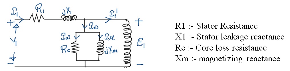
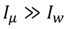
- In an Induction machine due to air gap between stator and rotor the magnetizing current drawn by the Stator is must be higher as compare to magnetizing current drawn by the transformer.
- hence
- So usually we ignore
 and only consider
  in the shunt branch.
 - The magnetizing Reactance of a Induction motor is much as less as compare to magnetizing reactance of a transformer.
Rotor Equivalent Circuit
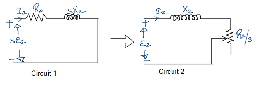
- The physical meaning of first rotor equivalent circuit is that the rotor frequency is sf due to which a factor of slip appear in emf as well as reactance but in the second circuit there is no factor of slip in emf and reactance which means the frequency of the rotor in the second circuit is taken as “f” instead of “sf”.
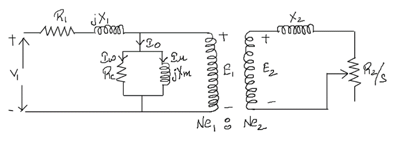
- In a transformer the frequency of primary and secondary winding is identical where as in a induction motor the frequency of stator winding is “f” whereas the frequency of rotor winding is “sf” so we cannot apply transformer principle directly to an Induction motor so we have to make the rotor frequency equal to stator frequency in order to treat the Induction machine as a transformer.
Question:- If both the Rotor equivalent circuit are identical then why is the real power in both the circuit unequal?
- Based on the frequency used in the two circuits we can observe that frame of reference for 1st circuit is rotor whereas the frame of reference for 2nd circuit is stator.
- If the frame of reference is rotor we cannot observe the rotor rotation but if the frame of reference is stator we can observe the rotor rotation.
- When frame of reference is rotor the mechanical power is zero since the rotor appears to be stationary and hence the net power input corresponds to the rotor Cu loss.
- When frame of reference is stator the net power input is equal to sum of rotor Cu loss and mechanical power developed because from Stator the rotation of rotor can be observe.
We generally ignore the core losses in the rotor

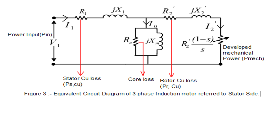
The power across the resistance  gives rotor Cu loss and hence the power across the remaining resistance gives mechanical developed power
I do agree with all the ideas you have presented in your post. They are really convincing and will definitely work. Still, the posts are too short for novices. Could you please extend them a little from next time? Thanks for the post.
Thanks for sharing superb informations. Your web-site is so cool. I’m impressed by the details that you’ve on this site. It reveals how nicely you perceive this subject. Bookmarked this web page, will come back for more articles. You, my friend, ROCK! I found just the info I already searched all over the place and just couldn’t come across. What a perfect web site.