- In Induction machine both the stator and rotor winding carry current and produce flux due to which the resultant air gap flux is obtained by sum of the flux of the 2 winding and this resultant flux is responsible for inducing an e.m.f in stator as well as rotor winding.
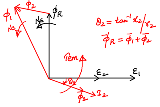
- In an Induction machine rotor number of turns are usually less then stator number of turns due to which magnitude of rotor emf is less then the magnitude of stator emf.
- When emf is induced in the rotor due to short circuited rotor winding current flows in the rotor winding and since the winding consist of resistance and reactance the rotor current will lag the rotor emf by a certain angle.
- The rotor flux
 will lie in the same phase as the rotor current.
- The torque is produced in such a direction that the rotor flux tries to catch the stator flux.
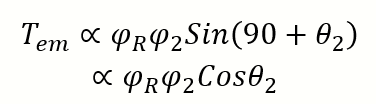
- To maximize the torque
 should be as small as possible and ideally should be zero which is only possible if the rotor winding is purely resistive and its leakage reactance is zero.
Phasor Diagram of Induction Generator
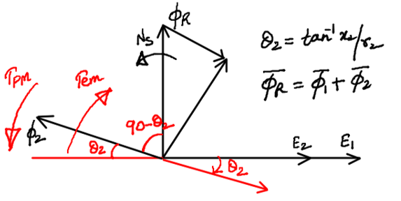
- In an Induction generator the direction of current flow in the winding is reversed as compare to a Induction motor so the flux developed by rotor current will now be in opposite direction to the current.
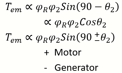
- As can be seen the direction of torque is such that rotor flux tries to catch the stator flux but it is opposite to the direction of rotation which is generally the case for a generator.
- In a motor develop torque supports the rotation where as in generator prime mover torque supports rotation develop torque opposes rotation.
My brother recommended I might like this web site. He was entirely right. This post truly made my day. You cann’t imagine just how much time I had spent for this information! Thanks!