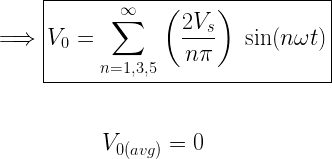
Transfers power from DC Circuit to another AC Circuit at required voltage and required frequency.
APPLICATIONS OF INVERTER
The applications areas of inverters such as:-
•Adjustable-speed ac motor drives
•Uninterrupted power supplies (UPS)
•Running appliances of ac used in an automobile battery.
•power transmission industry such as reactive power controllers and adaptive power filters
TYPES OF INVERTER
CURRENT SOURCE INVERTER (VSI)
- Unidirectional and bipolar
- Good Short Circuit Protection
- Load current depend on source current
- Load Voltage depends on load
VOLTAGE SOURCE INVERTER (CSI)
- Unipolar and Bidirectional
- Short Circuit Damages
- Load Voltage Depends on Source Voltage
- Load current depends on load
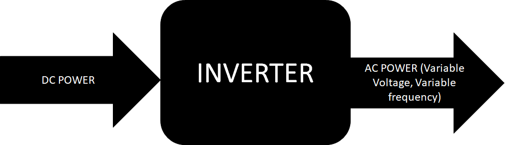
SINGLE PHASE HALF BRIDGE VOLTAGE SOURCE INVERTER
OPERATION
- Switch S1 is ON for the time duration of 0<t<T/2
- Switch S2 is ON for the time duration of T/2<t<T
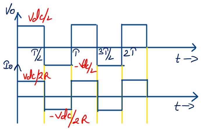
- When Switch S1 is turned ON the instantaneous voltage across the load Vo = Vdc/2.
- When Switch S2 is turned ON the instantaneous voltage across the load Vo = -Vdc/2
- Antiparallel diode does not change voltage polarity but reverses current direction.
QUADRANT OPERATION OF SWITCH AND DIODE OF SINGLE PHASE HALF BRIDGE VSI
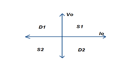
•Switch (S1 & S2) Provides Operation in 1st and 3rd quad
•Diode (D1 & D2) Provides Operation in 2nd and 4th quad
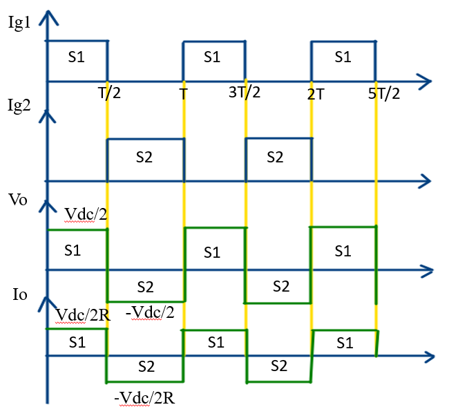
- Ig1 and Ig2 is called a gate pulse which is used for turned on the switch S1 and S2
- In case of Resistive load during the period of 0<t<T/2 the output voltage across the resistive load is Vo = Vdc/2 and during the period of T/2<t<T the Vo = -Vdc/2.
- In case of Resistive load during the period of 0<t<T/2 the current flowing through the resistive load is Io = Vdc/2R and during the period of T/2<t<T the Io = -Vdc/2R.
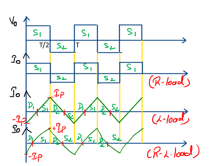
- In case of purely (inductance load) L load current Io symmetric about t-axis so that dc component = 0 and current is linearly from minimum peak current (-Ip) to maximum peak current (+Ip).In this case diode D1 is conduct in 0<t<T/4, switch S1 is conduct in T/4<t<T/2, Diode D2 is conduct in T/2<t<3T/4 and switch S2 is conduct in 3T/4<t<T.
•L load (0<t<T/2)
V=Vdc=Ldi/dt
L[Ip-(-Ip)]/T/2=Vdc/2
Ip=Vdc/8fL
In case of R-L load exponentially rise from (-Ip to +Ip). In this case diode D1 is conduct in 0<t<T/4, switch S1 is conduct in T/4<t<T/2, Diode D2 is conduct in T/2<t<3T/4 and switch S2 is conduct in 3T/4<t<T.
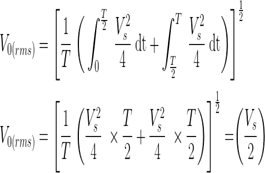
- For any type of Load, Output Voltage waveform will remain same but Current waveform depends on the nature of the load.
Or
Output Voltage waveform is Half Wave Symmetric hence all even harmonics are absent.
In case of purely resistive load
In case of R load, L load and R-L load.