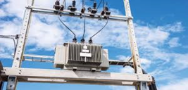
A transformer (Fig. (A)) is a static device that consists of two or more stationary electric circuits interlinked by a common magnetic circuit to transfer electric energy between them. The transfer of energy from one circuit to another takes place without a change in frequency.
What are Step-up and Step-down Transformers?
- This is a very useful device, indeed. With it, we can easily multiply or divide voltage and current in AC circuits. Indeed, the transformer has made the long-distance transmission of electric power a practical reality, as AC voltage can be “stepped up” and current “stepped down” for reduced wire resistance power losses along power lines connecting generating stations with loads.
- At either end (both the generator and at the loads), voltage levels are reduced by transformers for safer operation and less expensive equipment.
- A transformer (Fig. (B)) that increases the voltage from primary to secondary (more secondary winding turns than primary winding turns) is called a step-up transformer.
- Conversely, a transformer designed to do just the opposite is called a step-down transformer.
Faraday’ Law of Electromagnetic Induction
It is a basic law of electromagnetism predicting how a magnetic field will interact with an electric circuit to produce an electromotive force (EMF). This phenomenon is known as electromagnetic induction.
Faraday’s First Law of Electromagnetic Induction
Any change (Fig. (C)) in the magnetic field of a coil of wire will cause an emf to be induced in the coil. This emf induced is called induced emf and if the conductor circuit is closed, the current will also circulate through the circuit and this current is called induced current.
Method to change the magnetic field:
- By moving a magnet towards or away from the coil
- By moving the coil into or out of the magnetic field
- By changing the area of a coil placed in the magnetic field
- By rotating the coil relative to the magnet
Faraday’s Second Law of Electromagnetic Induction
In (Fig. (D)) it states that the magnitude of emf induced in the coil is equal to the rate of change of flux that linkages with the coil. The flux linkage of the coil is the product of the number of turns in the coil and flux associated with the coil.
Principle of Transformer Operation
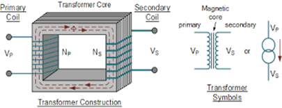
- Consider two coils 1 and 2 wounds on a simple magnetic circuit as shown in Fig.1.1.These two coils are insulated from each other and there is no electrical connection between them.
- Let N1 and N2 be the number of turns in coils 1 and 2 respectively. When a source of alternating voltage V1 is applied to coil 1, an alternating current Io flows in it. This alternating current produces an alternating flux Ჶm in the magnetic circuit. The mean path of the flux is shown in Fig 1.1 by the dotted line. This alternating flux links the turns N1 of coil 1 and induces in them an alternating voltage E1 by self-induction.
- Thus, all the flux produced by coil 1 also links N2 turns of coil 2 and induces in them a voltage E2 by mutual induction. If coil 2 is connected to a load then an alternating current will flow through it and energy will be delivered to the load. Thus, electrical energy is transferred from coil 1 to coil 2 by a common magnetic circuit.
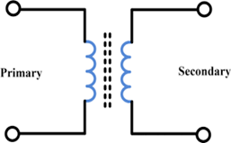
Primary Coil which receives energy from the source of AC supply.Secondary coil or secondary winding which is connected to load or delivers energy to the load. The circuit symbol for a 2 winding transformer is shown in Fig.1.2. The two vertical bars are used to signify that magnetic coupling between the windings.