Fuse: It is a device used in circuit for protecting electrical equipment against overloads and/or short circuits.
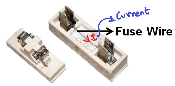
As we can see in Fig.(A) when high current flows through the system then heat produced melts the wire of fuse and thereby open the circuit. If “I” (current) flows through fuse wire
HEAT PRODUCED = (I2 *R)*T
Where R = Resistance through fuse wire.
T = Time of duration
and if HEAT PRODUCED > THERMAL LIMIT then fuse melt down.
Following points are considered while designing fuse wire
- Material used are Aluminum, Tin, Copper, silver, lead etc. or alloys.
- Cross sectional area is directly proportional to the rating of current.
- Length of fuse wire (L).


Fig C shows when fuse wire melts.
Electric Field = V/L
If V/L > dielectric strength of material then material break down.
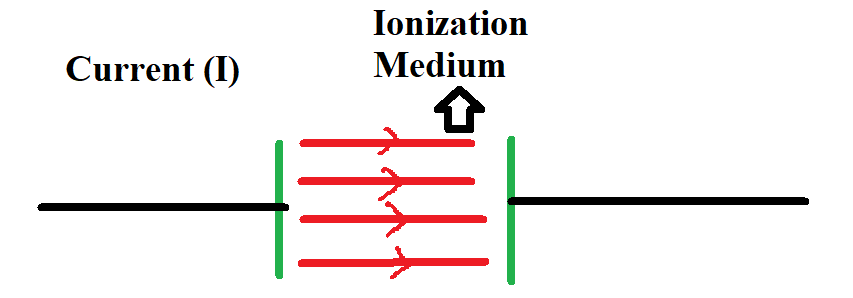
Here Ionization formed and circuit is again closed.
- Electric Field is directly proportional to dielectric strength.
- L (length) is directly proportional to voltage rating.
- Cross sectional area is directly proportional to current rating(I).
When Heat produced > thermal limit (Q)
(I2 *R)*T > Q
T > Q/(I2 *R)
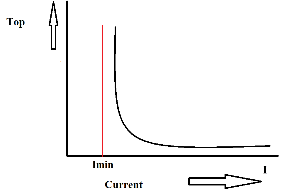
As you can see in fig. (E), Time taken by fuse to operate (Top) is directly proportional to 1/I2.
Imin = Minimum Fusing Current, for I < Imin, fuse does not operate
If Temperature < melting point, fuse is safe for fuse to operate should be I > Imin
Fusing Factor = (minimum fusing current/rated current of fuse) > 1